|
|
|
|
|

|
|
|
|
|
|
|
|
|
|
|
tutorial: firmware bootloader for Bolt 18F2550 system, programmable through USB port.
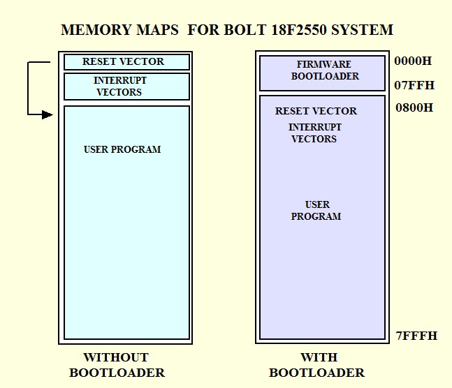
This firmware is called "Bootloader" and comes factory preloaded on Bolt 18F2550 microcontroller. The figure below shows in purple, the memory map of the 18F2550, preloaded with bootloader. The Bootloader occupies approximately 2K bytes in the bottom of the FLASH memory of the 18F2550, locations 000H...7FFH . This area should not be used by the user application program. The 18F2550 contains a total of 16K words of 16 bits (32 Kbytes) in his code memory.
Using this firmware you can transfer the executable files (.hex) from the PC or Laptop to the flash memory of the 18F2550 via the USB cable, and using the software Bolt v.1.0.1. This software already has its necessary drivers and automatically detects (plug and play), the presence of the Bolt module with its bootloader. The Bolt module can operate in two modes: "Bootloader mode" in which it is ready to be programmed, and "User mode" which automatically executes the application program. Both modes are user configurable via a jumper on the Bolt card. For more information, please refer to Bolt 18F2550 System Programming Manual The projects and programs developed to test the system, were implemented using the C18 compiler version 3.40 and MPLAB IDE from Microchip v.8.63. The following firmware .hex file is factory preloaded on the chip 18F2550: Boot20MHz.hex, firmware bootloader for 18F2550, external crystal 20 Mhz Boot8MHz.hex, firmware bootloader for 18F2550, external crystal 8 Mhz Firmware Bootloader Source Files.zip CONFIGURATION REGISTERS The 18F2550 microcontroller has 14 configuration registers of 8 bits each. Such registers can enable and configure many features of the microcontroller. The firmware preloaded in the system already contains the values listed below for each of the 14 registers. Here it is important to emphasize that, even though the system operates with an external 20 MHz crystal, the effective speed of execution of the program is 48 Mhz, precisely because of its configuration for the PLL frequency multipliers circuits. To see the details of the function of each of the bits in each register, please refer to the manual PIC18F2550 Datasheet.pdf pages 286-295. PRELOADED VALUES IN FIRMWARE BOOTLOADER FOR BOLT 18F2550
|