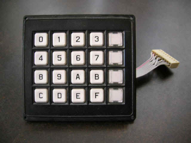
project: interface to a matrix 4 x 4 keypad
Theory of
functioning:
The shown
example is for a 16 keypad GREYHILL 86JB2-203. Unfortunately, there is no standard
connectors for keypads, and each model has a different hardware wiring, and a different
control subroutine.
HARDWARE
DIAGRAM AND INTERFACE WITH EDUPIC 16F84 MODULE
The keypad is
organized as 4 rows (X1...X4), and 4 columns (Y1...Y4), so that each key is
identified by the intersection of a row and a column. In the diagram you may see the
asignment of each signal to PORT B of 16f84.
The subroutine that controls the keypad has 2
sections: the "detection" part, in which the programs detects that a key was
pushed, and the "identification" part in which the programs tells the ASCII code
of the key that was pushed.
The technique to detect a pushed key, is to
scan columns Y1...Y4, writing 0111, 1011, 1101, 1110 , and then reading rows X1...X4 each
time. If no key is pushed, the reading in X1...X4 will be "1111". But when a key
is pushed, the reading in X1..X4 will be different to "1111". Next step is to
convert the row-column code of the key to its ASCII code through a "look up
table". Below you can see the relationship between the row-column code and the
ASCII code of each of the keys.
RB0..RB7 Hexa
KEY
RB0..RB7 Hexa
KEY
11101110
EE
“0”
10111110
BE
“8”
11101101
ED
“1”
10111101
BD
“9”
11101011
EB
“2”
10111011
BB
“A”
1110 0111
E7
“3”
10110111
B7
“B”
11011110
DE
“4”
01111110
7E
“C”
11011101
DD
“5”
01111101
7D
“D”
11011011
DB
“6”
01111011
7B
“E”
11010111
D7
“7”
01110111
77
“F”
CONECTION OF KEYPAD TO EDUPIC MODULE: the
header 16x of EDUPIC has a diagram of signal as shown. You must use pins 2, 4, 6, 8, 10,
12, 14, and 16. Please note that the numbering of the pins in the HEADER is different from
the IC DIL standard. Even pins are aligned in left column of header and odd pins are
aligned in right column.
Also remember that this particular
diagram is good only for the the GREYHILL keypad model 86JB2-203.
If a different keypad is connected, then the diagram and the look up table will change.

HARDWARE DIAGRAM FOR HEADER 16 X
TEST PROGRAMS: Several test programs for this keypad are listed. Only the .ASM source
program is given, so you must assemble before loading in EDUPIC. We suggest starting
with version 1, and then go on util you reach version 4, because the complexity of each
routine increases. The files are:
teclado1.asm
teclado2.asm
teclado3.asm
teclado4.asm
|