![]()
![]()
![]()
![]()
![]()
![]()
![]()
![]()
![]()
![]()
![]()
|
|
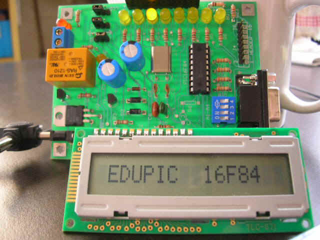
project: LCD interface for 16F84
Theory of operation: The LCD es presently the cheapest and reliable circuit to dipsly data in a monitoring process. Its interface with microcontrollers is made throug a 14 pin standard connector, which means all manufacturers have the same signals asignment and same command codes. In the LCD you may display data such as for example date and time, and also variables such as level, pressure, flow, temperature, etc. An LCD may also show the options that the user may choose when programming the system. The circuits of the LCD includes a character generator ROM, which stores all codes of the matrix dot pattern in the text characters (5 x 7 or 7 x 9). Also included, there is a RAM memory which stores the ASCII codes of the characters that will be displayed. Hardware: The hardware diagram is shown below. In its simplest application, you may only wish to write on the LCD, and then the pin 5 si always connected to ground. Port B signal RB0...RB7 are used to send data and commands to the LCD. Port A signals RA1 and RA2 are used as control signals. All signals are TTL (0 to 5 volt), exception made of the intensity control signal in which ground is applied for the gratest value of intensity and 5 volt for the least value. In the EDUPIC module, such value is preadjusted with a resistor divisor of 100K and 1K (R26 and R25).
Operation: In the 14 pin interface, 8 (DB0...DB7) are command or data signals. All data is in ASCII code and are written in the LCD in the same order as they are sent. These same signal are also used to send commands to the LCD. In the first table shown below, the function of each signal is given. In the second table, the commands more frequently used are stated.
To write in the LCD, from the 16f84, you must follow a programming sequence: 1. with RA1=RS=0, send the inicialization commands shown in the table to LCD. To send a comand, you must first write the code in the PortB, RB0...RB7 bits, wait 10 miliseconds and then generate an active low 10 miliseconds pulse in EN (RA2). EN is a normally high signal. 2. with RA1=RS=1, you may now write ASCII data in the LCD. The procedure is the same: write data in RB0...RB7, wait 10 ms, and give an active low pulse of 10 ms in the RA2 signal. If you wish to write in the 1st row of LCD, you must then first send the ROW1 command (80H). If you wish to write in the 2st row of LCD, you must then firs send the ROW2 (C0H) command. Kinds of LCD: The most common LCD are either 16 x 1 format or 16 x 2 format. The 16 x 1 display are usually electrically divided in two sections of 8 characters each. These sections are operated as if they were two different rows. If you wish to write in the first section, you must first send a 80H command, or a C0H for the second section. The 16 x 2 LCD displays are easier to handle because both rows are separated. Individual cells in each row may as well be addressed by sending beforehand the proper command. For example, if you wish to write in cell number 5 of 1st row, you must then first send an 85H command or a C7H command for cell number 7 of second row. Firmware: As examples of the above mentioned, 3 test programs are given to be stored in the FLASH memory of the 16f84. The programs are written in the source files .ASM, so you'll have to assemble them first in order to obtain the .HEX, using WINPIC to transfer them to EDUPIC. -to handle a 16 x 2 LCD: lcd2.asm -to handle a 16 x 1 LCD: LCD16X1V2.ASM -to write a 256 character message to a 16 x 1 LCD. The message has a circular dynamic scrolling movement. You may wish to write a different message by changing the ASCII data in the table of the program: LCD16X1V4.ASM
|