|
project: proximity
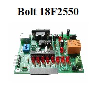
infrared sensor with 3 modes of operation, for Bolt 18F2550
system.
Introduction:
In a previous project,
an infrared remote control was described,
based on the circuit
TMF5360 or
TSOP1736,which integrates
a photodiode, as well as a demodulator for 36 Khz signals. This
control was implemented with a standard RC-5 remote control
handset and operates up to a distance of 10 meters.
Description:
In this project, using the
same
TMF5360 infrared
receiver and an infrared diode, a proximity sensor circuit was
designed. The circuit connects to the LCD port in
Bolt 18F2550
system and permits to detects objets from distances
up to 50 cms.
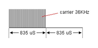
The principle of operation is to generate,
by means of the firmware in the microcontroller, a continuous stream of
30 pulses modulating a 36 khz carrier, each pulse with a duration of 835 us, and followed by a
space of same duration, as shown in the image below. To generate
such signal, the PWM (Pulse Wide Modulation) function contained
in the 18F2550 microcontroller is used.
This signal is emitted by
the infrared diode TN153BF, reflected by the near objet and detected by the infrared receiver
TMF5360. The 36 khz demodulated signal is analyzed by an
algorithm in the firmware of the 18F2550 microcontroller, which
subsequently activates the relay, when detecting a valid signal.
The proximity sensor may
detect the signal reflected by the objet up to a distance of 50 cms, and operates in 3 modes, configured by
the microswitches SW1..SW4 of the Bolt board.
|
|
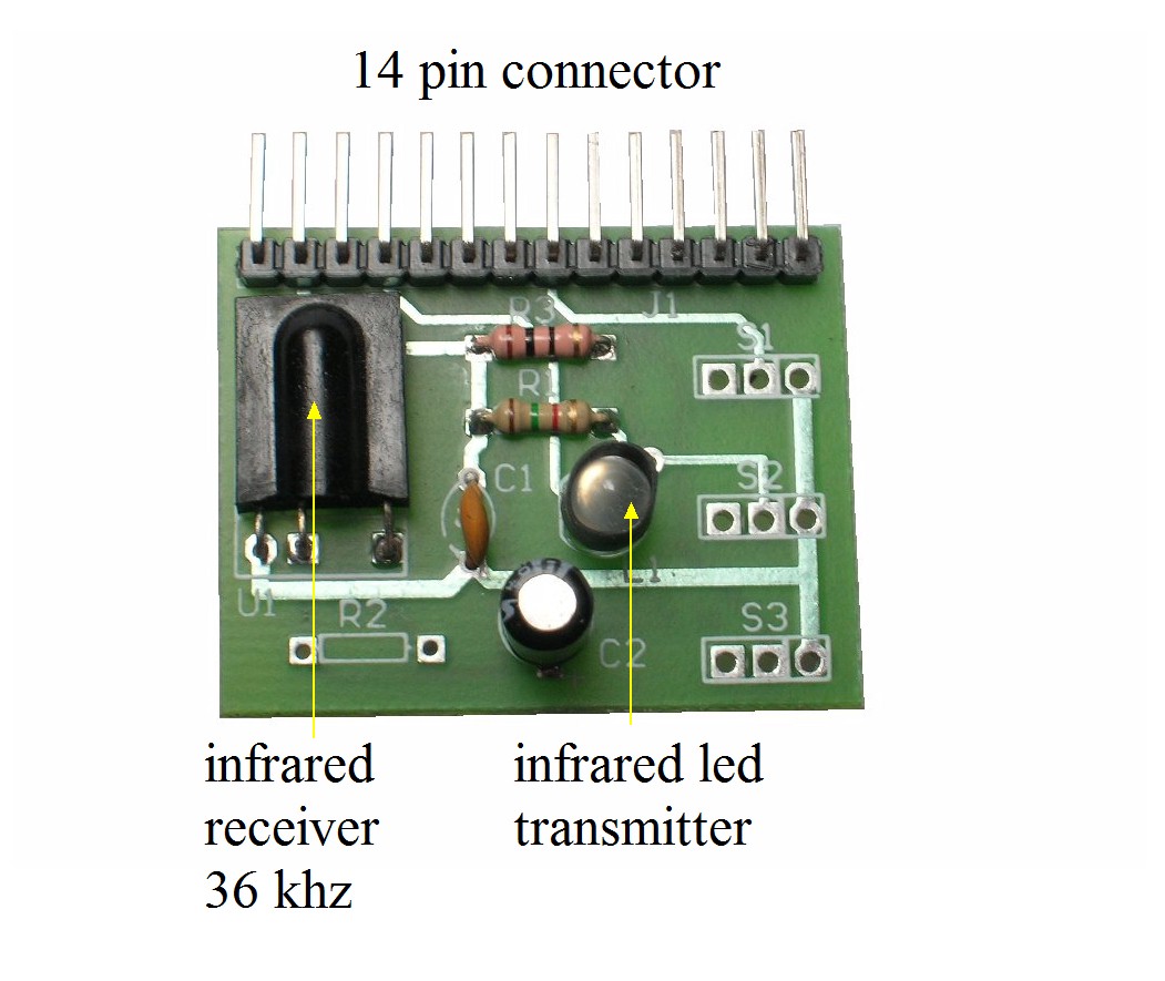
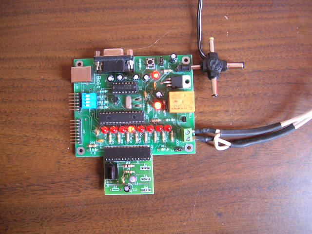
The
proximity sensor circuit connects to the LCD
port of 14 pin of the Bolt 18F2550 board. The
infrared diode is covered with a piece of
termofit to concentrate the energy of the signal
in one direction. The value
of the 1.5 kohm R1 resistor may be modified in a
range of 1 kohm to 2.2 kohm to increase or
decrease the
transmitting power of the infrared diode.
However, too much power
to the infrared signal may derive in an
unstable behavior of the circuit, given that the
IR emitted signal may be reflected by
walls or distant objects and reach the TMF5360, triggering the
relay even in the
absence of a near object. |
|
|
By means
of the 4 dip switches (blue module in the Bolt
board)SW1..SW4, the user may program the
following 3 modes of operation:
Mode 1 PROXIMITY DETECTOR
MODE (SW1..SW4 OFF): relay is active when an
object nears a distance of 30 cm or less of the
infrared LED. Remains active until the object
moves away.
Mode 2
TOGGLE SWITCH MODE (SW1=ON, remaining OFF):
Activates relay if the object is near.
Deactivates if the object is near again and so
on.
Mode 3
TIMER MODE (SW1=ON, SW2=ON, remaining OFF):
activates the relay for 6 seconds when the
object is near. |
|
|
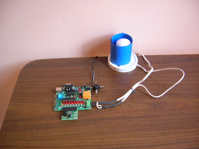
The
circuit will function with more accuracy with an
external wall transformer connected to the Bolt
board, due to the on board 5 volt regulator.
Average distance of the object to the infrared
sensor to trigger the relay will be about 40- 50
cms. It is also
possible to feed the board from the USB cable of
the computer. In this case the distance of the
objet to the infrared sensor for detection will
be about 25-35 cms.
A lamp was connected to
the relay terminals to make testing.
|
|
|
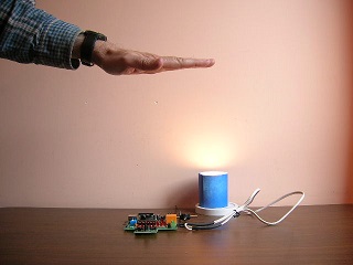
During
testing, you will obtain different results
depending on the object nearing the infrared
sensor. The larger the object you will get more
power of signal reflected, so the
needed distance for detection will be larger.
Also, a white or pale
objet will reflect the infrared signal with more
efficiency than a dark object.
With a white sheet of
paper reflecting the infrared signal, you may
obtain distances aproaching 60 to 80 cms. |
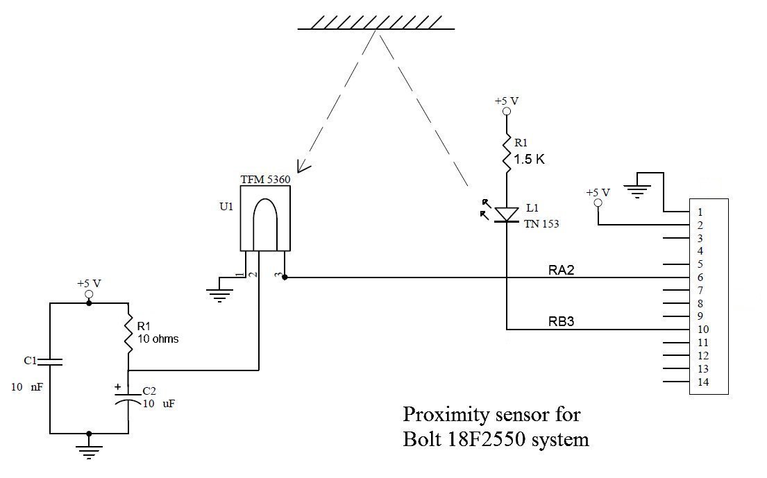
ELECTRONIC DIAGRAM
|