|
|
|
|
|

|
|
|
|
|
|
|
|
|
|
|
|
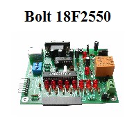
Control of ISCE014A, 8 relay module, using its asynchronous serial port, with Bolt 18F2550 system
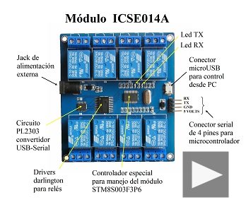
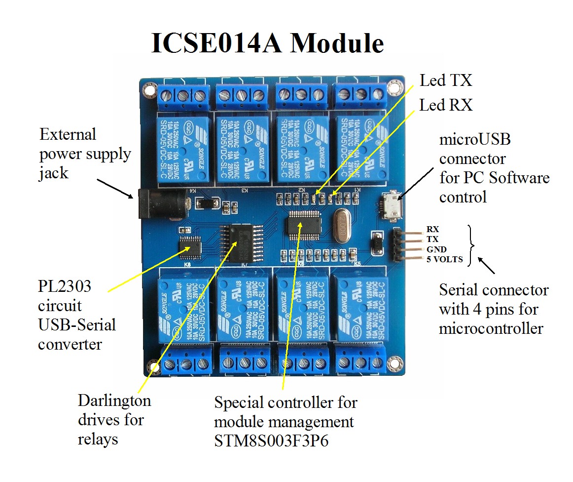
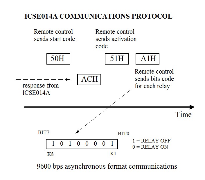
Figure 1: The ICSE 014A module is a versatile and sophisticated circuit for remote control of 8 relays. Among its facilities is the ability to connect -via an asynchronous serial port with TTL levels- to a microcontroller system. Activation of the relays is performed by means of a simple protocol, which is described below. In this project, test programs were performed with Bolt 18F2550 system.
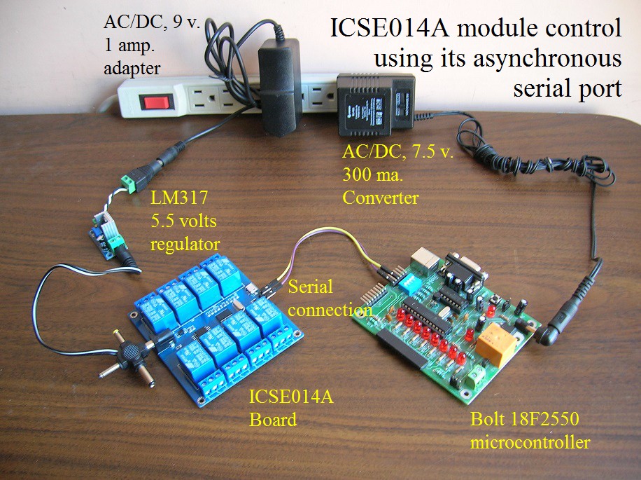
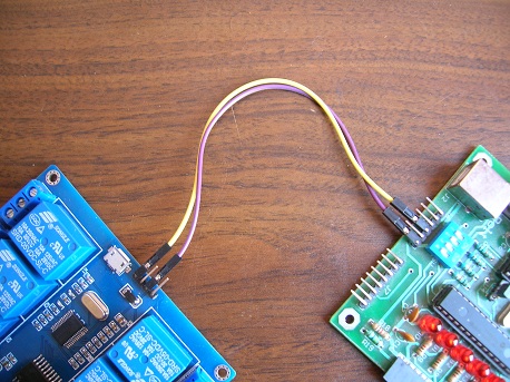
Figure 2: to operate the ICSE 014A module, connect the devices as shown in the photo. The maximum consumption of the module is 700 ma (with all relays activated). We recommend using an external source regulated to 5.5 volts to power the board and avoid overloading the voltage of 5 volts from the USB port on the computer, since USB 2.0 ports only provide up to 500 mA. Important note: on powering up the ICSE014A board, all relays are activated automatically by the firmware, that is, consumption will be the maximum.
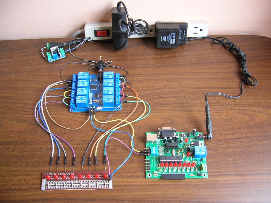
Figure 3. To perform the final tests, a small board with witness leds connected to the contacts of each relay is implemented. The test program turns consecutively on and off each of the relays, with visual check on the LEDs.
|