|
|
|
|
|

|
|
|
|
|
|
|
|
|
|
|
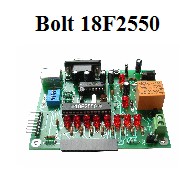
Bolt 18F2550 system LCD and keypad
interfaces
|
|
|
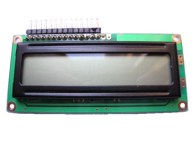
LCD 16 X 1
|
The LCD is
currently the cheapest and
most reliable circuit
to display data in a
monitoring and
control process. Its interface
with the
microcontroller takes
place via a
standard 14 pin connector. The LCD display 16 x 1, included in Bolt 18F2550 system kit is electronically organized as 2 rows of 8 cells each, to form the 16 character display. All manufacturers of liquid crystal display, LCD, have standardized the 14-pin connector, as well as the control commands for operating the same. The LCD can display data such as time and date, as well as values of variables such as level, pressure, flow, temperature, etc. |
|
|
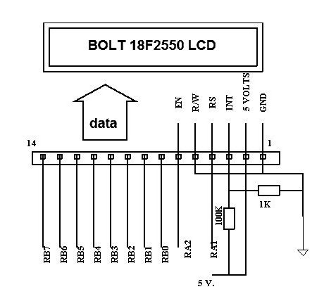
Intensity of the characters shown in display is set by the voltage
divider of 100K and 1K resistors. This voltage was calculated to work with the
LCD 16 x 1
included in Bolt 18F2550 kit. In the 14-pin interface, 8 signals of Port B (RB7...RB0) are used to send commands or data to LCD. Signals RA1 and RA2 are used as control signals. Data is handled in ASCII codes and written into the internal LCD RAM memory sequentially. We provide several C functions to control the LCD using Bolt 18F2550 system. The library is: 18F2550BOLT.h You may see examples on how to use this functions in this simple test programs: |
|
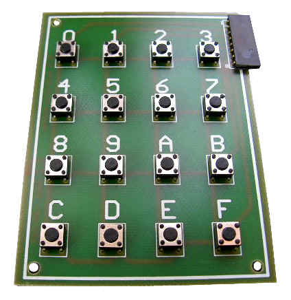
HEXADECIMAL KEYPAD
|
There is no standard
connection for
keypads in microcontroller
systems, and each
device requires a certain hardware
configuration and a different
ANSI C function drivers. The simplest configuration is known as a matrix with 4 rows and 4 columns, for a total of 16 buttons. The hexadecimal, inexpensive keypad shown in photo at left, may function with any microcontroller in the simplest way. Signal assignments are shown in the figure below. |
|
|
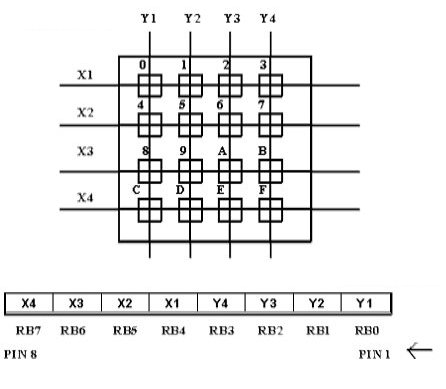
The keypad is organized as 4 rows (X1...X4) and 4 columns (Y1...Y4), so that each key is identified by the intersection of a row and a column. Signals in Port B, RB0...RB3 are programmed as output, while signals RB4...RB7 as inputs. The keypad control program has two parts: first, the program detects that a key was pressed. In its second part, the program identifies which key was pressed and converts to an ASCII code. We provide several ANSI C functions to control the keypad connected to Bolt 18F2550 system. The library is: 18F2550BOLT.h You may see examples on how to use this functions in this simple test programs: C18-Bolt-18F2550-All-Test-Programs.zip
|