|
|
|
|
|

|
|
|
|
|
|
|
|
|
|
|
project: build a 7 segment display module |
|
|
|
|
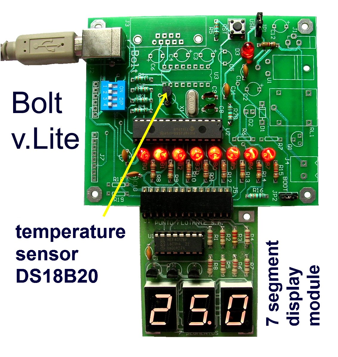
Overview: When you need to display large numerical information in a microcontroller system, the 7 segment LEDs modules are the cheapest circuits, and the electronic design is quite simple. The module may be connected to a standard LCD interface, so your system may work either with an LCD, a seven segment display or a 7x10 led matrix module. This entire module includes three 7 segment displays, 8 resistors, 3 BC337 transistors and a 4017 decade counter circuit. All components can be purchased at any electronics store. The connection to Bolt 18F2550 or Bolt v.Lite system is direct through the standard connector for 14 pin LCD. |
|
|
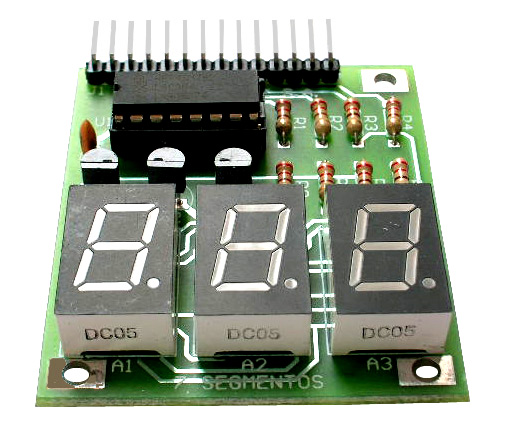
PCB of 7 segment display:
|
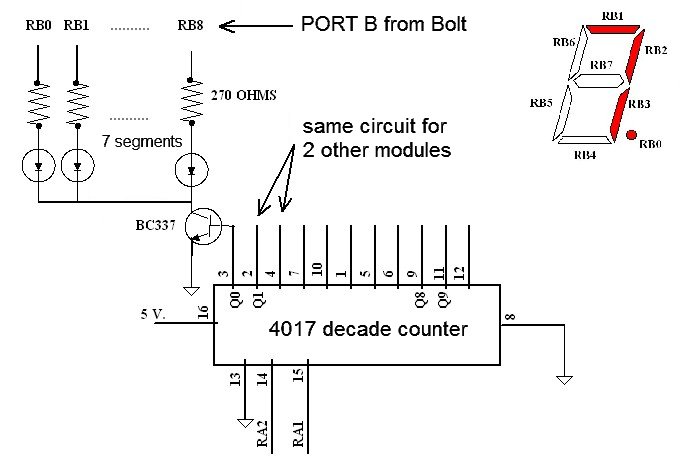
Multiplexing technique: the
7 segment modules
are activated one by one in
sequence, through
a decade counter 4017. This multiplexing is performed at a frequency of about 100 Hz, giving the impression to the human eye that the LEDs are permanently on. The pattern of activated segments in each module is defined by the state of PORT B port outputs (RB0...RB7). There are 2 control signals for the 4017 counter: RA1 for master reset (MR) and RA2 for activation (CP0) of each module through its corresponding transistor. |
|
|
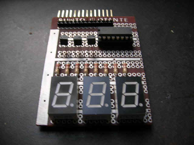
Prototype of 7 segment display:
|
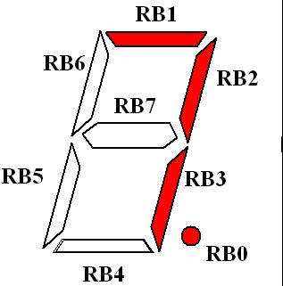
Electronic circuit: the block diagram below shows the electronic module. The design was carried out for 3 modules, but may be connected up to 10. All modules are common cathode and connected as indicated in the diagram. A BC337 transistor is used to activate each module. The current limiting resistors of 270 ohms are suitable for handling 3 modules. |